Update on Flexinol (Muscle Wire)

(This post is an update on my last post on the use of flexinol ( a type of muscle wire) with arduino)

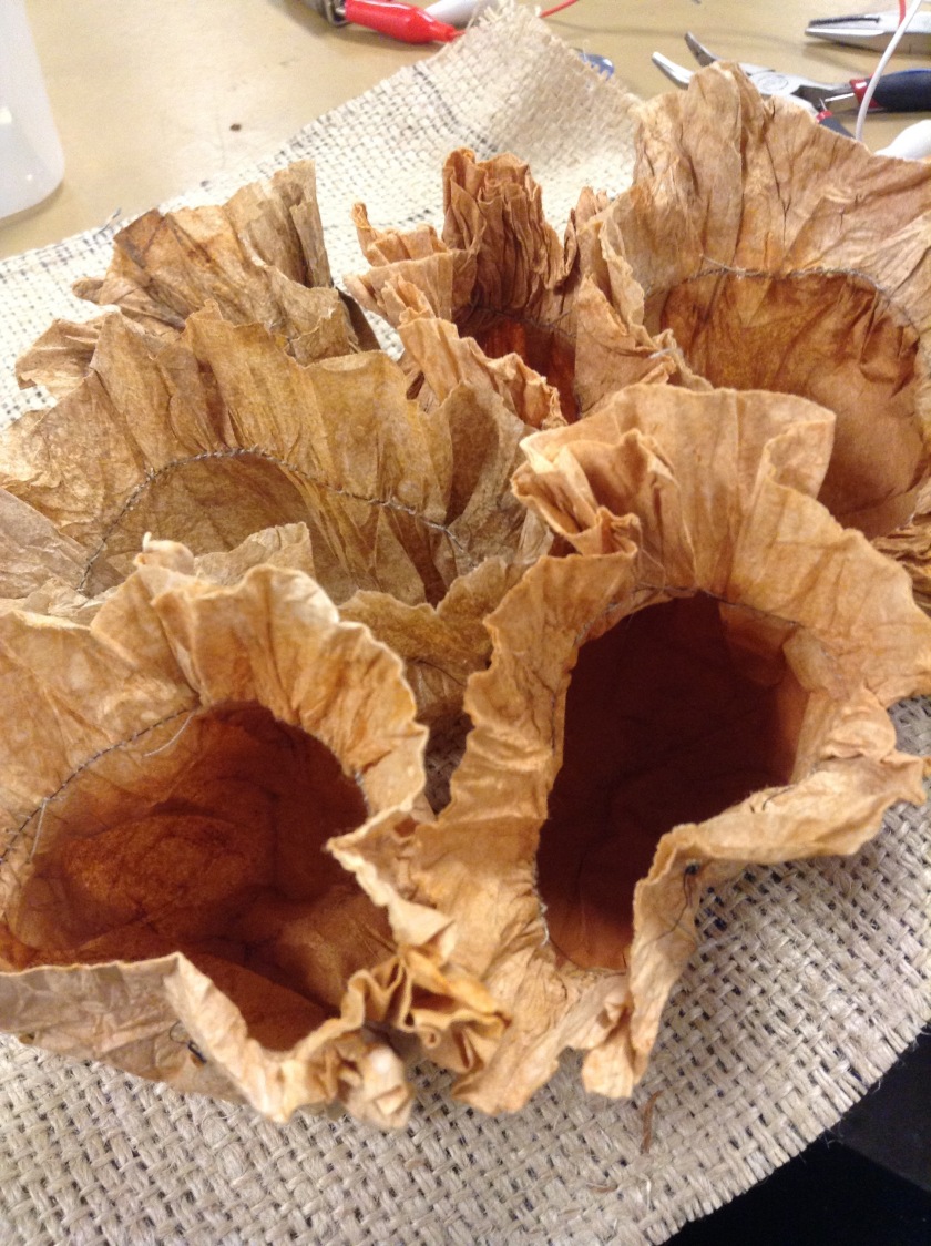
During the last month, I have been continuing to work on utilizing flexinol to create kinetic sculpture. At the time I wrote my last post, I had started to incorporate the sculptural forms I had created with an Arduino board to make a rhythmic “pulsing” movement. I was struggling at that point to direct enough voltage to the muscle wire forms to make more than one form at a time move (about 4-5 inches of muscle wire). I can however, get the forms to move as a group manually with a 9 volt battery:

Unfortunately, I am still struggling to get this affect while connected to an arduino. I also tried switching from arduino to an ATTiny85 micro-controller to save space for these relatively small sculptures, which I also struggled with. I am having difficulty finding the right technique for getting enough voltage (about 9 volts) to the muscle wire.

Besides the electronic aspect of the project, I have also improved my technique for securing the muscle wire to the rest of the wiring (as it cannot be soldered). Earlier, I had just secured the muscle wire by twisting it with the the connecting wire. This sort of did the job, but it was not very secure and I found myself having to fix connections frequently. I took a tip from a friend and started to secure the connection to the muscle wire by crimping small brass fasteners:

IMG_1550

IMG_1549

I also made sure to start sewing the normal wire into the forms, especially at the base of the forms, where they would transition to the other electronics, to prevent shorts.

In addition to the more secure connections, I also have thought more in-depth on how I would like these forms to be installed within a space. In my first post, I had essentially just   placed the forms and electronics on a ledge with a piece of canvas to hide the electric components. However, I feel that it is important for this project that the forms be very well integrated into a space. I became interested in muscle wire in the first place because of its ability to create movement that seems natural to casual viewer, and I think to properly create that affect the placement and installation of the forms need to feel just as “natural”. After trying a few different options for the installation, I finally decided that the best way to go about it was to always install at the floor or ceiling of corners. This allows for the most volume behind the forms to hide electronics, while only having to cover a small surface area in front:


The forms are attached to a piece of canvas that is sewn into a triangular frame that can be set into the corner:

I like this solution because it allows me to utilize the existing geometry of a space to fully integrate the sculptures into their environment.

From here, I would still like to get the electronics functioning how they are intended to. I will make another update when that happens!

Flexinol + Arduino

Lately I have been experimenting with muscle wire with Arduino.

For those who haven’t heard of it, muscle wire is a type of shape memory wire made from the metal alloy nitinol. There are a few different types/brands available online, but the basic idea is when supplied with a current, the muscle wire is able to change form. I personal was interested in its potential for creating organic kinetic sculptural forms that have a feeling of “life” when controlled through Arduino.

The biggest problem I have encountered is understanding the limitations and properties of  muscle wire. Before you buy, make sure you understand which type you are getting. I have been using the brand Flexinol (which can be found on robotshop.com), which comes pre-annealed and is able to both contract (when supplied with a current) and relax (when their is no current). A lot of muscle wire does not come pre-annealed, and has to be set to contract to a certain shape using jigs, and will not relax once the current is gone. If you want the “contract and relax” motion, make sure to purchase Flexinol specifically!

Here is a visual of the type of motion you can achieve with Flexinol (from the YouTube channel of Jie Qi, who has many great examples of projects you can do with Flexion):

I found that once you have a form you would like to work with, a big challenge is creating the proper tension to get noticeable movement. You can see in this photo how closely I have sewn the wire into my forms:

IMG_1381

(As a side note, I made these forms from coffee filters)

Here is a video of the first form I was able to make move:

In this video, I did not have the muscle wire hooked up with Arduino yet. I was simply attaching alligator clips to either end of the wire and to a 9v battery. Be careful when testing: only connect the wire to your battery for a few seconds at a time (I would say 5 seconds at the absolute maximum). If you connect it too long, you will damage your muscle wire. I also found that if you held the current to long, the wire would get so hot that it would start to burn the paper and thread that it was sewn into, and I would have to re-sew the form.  If you want to connect more than one form at once, I found that parallel circuits worked better than series circuits.

Once you have the forms you want, you can try controlling it with Arduino, allowing for the movement of your wire to pulse to a specific rhythm or be controlled by various input from sensors. The two important things: use pulse with modulation, still only allowing a few seconds of current through the wire at one time, and use a transistor.

Here is one form controlled by Arduino:

Here are pictures of the circuitry:


Unfortunately, I was not able at this point to make more than one form move at one time. I need to experiment with other transistors or another method of getting more voltage to the forms, because the setup I have now is not quite doing it.

Obviously I am still a beginner (not just to muscle wire, but to electronics in general), so I would love any suggestions or feedback! I am determined to get this project working, so I will make an update whenever that happens.

Printmaking + Digital Fabrication

This semester I am working on a research project/technical investigation on the potential of using CNC machining to make printmaking relief and intaglio plates. I am specifically interested in using 3-axis operations (rather than 2 1/2, which would give you the same affect as a traditional relief woodblock print) to create 3 dimensional plates for embossing. Through a combination of 3D scanning, 3D modeling, and photography, this will allow me to create prints with the physical impression of objects, textures, and surfaces from the physical world.

These are some of the images I have been working with to create test models. I am interested in capturing textures from the ground, such as crumbled sidewalks, piles of debris (usually salt due to the time of year and my area of residence), weeds, etc. While the above edits may not be considered good photography, I am experimenting with how different edits (such as extremely high or low exposure) affects the resulting 3D model.

To create the model, I am currently playing around with the affects of the “heightfield” tool in Rhino, which creates a 3D mesh from photos, based on the values in the photo (which is why how I edit the photo is important). I have also experimented with making a 3 color live trace of an image in Adobe Illustrator and extruding the resulting layers in Rhino.

Heightfield tool:

full-screenshot

Live trace:

live-trace-screenshot

The live-trace technique is good because I have more control over the exact dimensions of the layers of the plate. However, the layers are all flat since they are straight extrusions from vectors, so it creates more of a “stepped” effect. The heightfield tool preserves more detail, and there are also settings in the tool that allow for some interesting distortion effects.

By limiting the number of vertices in the model, you can create a “faded” appearance:

faded-screenshot
models from heightfield tool at 40, 50, 60, 70, and 80 vertices per inch

You can take this feature to quite an extreme:

distorted-screenshot

Here are some shots of a simulation in RhinoCAM of how one of the plates will look when milled:

mill-simulation
5/64 diameter endmill


mill-simulation-detailed
1/32 diameter endmill

Obviously I am working at extremely high detail, the above simulation is only on a 5 in long piece and it still captured everything from this model (the example on the right):

detailed-screenshot

This model is also at a very shallow depth (about .02″), but I will definitely play with deepening that. There is somewhat of an interplay between wanting to know how detailed and shallow and intricate I can make a piece through milling (and how much small detail I can emboss in paper), but also wanting to get as much depth in my print as possible. I will definitely need to make a few different pieces with this project.

From here, I am ready to start making these models physical. I will probably start by making at least a couple 3d printed versions, just because of the time investment required to mill even small surface areas at this level of detail.